
Raymarching Basics. Camera
In the previous chapter we have set up a sandbox Godot project. We have created a fullscreen shader and have used it to display an opaque red color. Quite boring.
In this chapter I will cover basics of Raymarching. I will provide you a very brief explanation of the technique and focus on implementing camera in the shader. You can jump to the code first and than see the explanation or vice versa.
Theory
Raymarching overview
Lets consider our real world. How do we see things around us? Light sources produce light. Light moves along the ray until it hits some object. Eventually it is either consumed by the object, reflected away from it or refracted. Either way, this beam of light somehow reaches your eye (or camera lens).
We can see objects because the light is reflected back to our eye. Without the light source we can see no objects.
We are going to simulate this phenomenon. But instead of tracing millions of rays from all the light sources (of which very few would hit the eye) we will do the opposite. We will shoot our rays from the eye and see what they hit. Than we will determine pixel color using the hit point, properties of the light source and of the object.

Now comes the tricky part. How do we know what our ray hits along its path? Well, we could:
- For each object find the intesection point with one ray at a time. We are going to pick the one closest to an eye. This is the raytracing technique.
If we have N objects and R rays than we have to perform N*M collision tests at worst. - Move along the ray with some steps and check whether or not we have hit some object. This is the raymarching technique.
Okay, so we are going with the second approach. You might ask “How do I pick a step?” and “How do I know that I have hit the object”? And here comes the brilliant solution.
Meet the SDF – Signed Distance Function (takes vec3 -> produces float). It accepts a point in space and tells how far away are we from the objects on the scene.
Here is an example: lets say we have 1 sphere. It is centered in (0, 0, 0) and its radius is 1. Now lets say that we have point (2, 0, 0). How far away are we from the sphere? The answer is
And in our example
How can we answer on “How do I know that I have hit an object?” If SDF returns small value (ex. 0.0001) – you are very, very close to an object. So close that you can say neglect it. If at any point along the ray SDF returns very small number – our ray has hit an object on a scene.
Lets answer on “How do I pick a step?” If you pick a constant step (say 1 unit each time) you have 2 problems:
- If you pick large step you are likely to overshoot your object.
- If you pick small step you are moving very slowly and can miss the 60 FPS goal.
And SDF comes to a rescue again! Lets say that SDF has returned 4. What does it mean? It means that an object is at least 4 units away from your current position, no matter the direction you are facing. It can be further but never closer. So why not march in the direction of the ray 4 units forward?

And here is full the answer: you move as far as the SDF tells you to. This way you will never overshoot the target and will move much, much quicker than with the small constant step.
Now, there is more stuff to consider. But this covers the essential basics. Please watch the video below (starting at 1:55) to gain even better intuition.
Camera
Camera is an object that has a position and a field of view. It represents our viewing window into the virtual world. My camera implementation is based on the video below.
If you’d prefet to read about camera, please follow the link: Ray-Tracing: Generating Camera Rays.
Coding
We are going to calculate ray direction in our fragment shader and display it as a color.
First of all we need a set of parameters that control our shader:
uniform float fov = 45.0; // the vectical field of view (FOV) in degrees
uniform vec3 cameraPos = vec3(0.0, 0.0, 5.0); // position of the camera in world coordinates
uniform vec3 front = vec3(0.0, 0.0, -1.0); // where are we looking at
uniform vec3 up = vec3(0.0, 1.0, 0.0); // what we consider to be up

Uniform variables can be changed outside of the shader (either from script or the Inspector tab). Later on we can manipulate camera from the game engine using keyboard and mouse (or touch on phones and tablets).
For now we will be doing no raymarching yet. We will merely set up a camera. For each pixel we are going to compute a direction that the ray is traversing in.
In the fragment shader add a new function. It will accept the screen resolution and a location of a pixel in normalized coordinates (in range [0, 1]) and produce ray direction:
vec3 getRayDirection(vec2 resolution, vec2 uv)
{
    ...
}
We start by computing aspect ratio of the screen and converting a view angle to radians and dividing it by 2:
vec3 getRayDirection(vec2 resolution, vec2 uv)
{
    float aspect = resolution.x / resolution.y;
    float fov2 = radians(fov) / 2.0;
    ...
}
After that we convert uv (nomalized pixel coordinates) to a range [-1, 1] and invert the y coordinate (because in Godot Y axis flows from the top to the bottom). We can obtain the contribution of the up and right vector:
vec3 getRayDirection(vec2 resolution, vec2 uv)
{
    ...
    // convert coordinates from [0, 1] to [-1, 1]
    // and invert y axis to flow from bottom to top
    vec2 screenCoord = (uv - 0.5) * 2.0;
    screenCoord.x *= aspect;
    screenCoord.y = -screenCoord.y;

    // contibutions of the up and right vectors
    vec2 offsets = screenCoord * tan(fov2);
    ...
}
Now comes the interesting part. We compute the unit front, up and right vectors and make sure they are orthogonal to each other. This creates a coordinate frame. We use it to compute our ray direction. Don’t forget to normalize it!
vec3 getRayDirection(vec2 resolution, vec2 uv)
{
    ...
    // compute 3 orthogonal unit vectors
    vec3 rayFront = normalize(front);
    vec3 rayRight = normalize(cross(rayFront, normalize(up)));
    vec3 rayUp = cross(rayRight, rayFront);
    vec3 rayDir = rayFront + rayRight * offsets.x + rayUp * offsets.y;

    return normalize(rayDir);
}
And we have our ray direction! Now, to test how this works we will display the direction as a color. However, because the color components should to be in range [0, 1] and the coordinates of the direction are in [-1, 1] we have to do one more conversion. Here is the main fragment shader function:
...
void fragment()
{
    vec2 resolution = 1.0 / SCREEN_PIXEL_SIZE;

    vec3 rayDir = getRayDirection(resolution, UV);
    // convert ray coordinates from [-1, 1] range to the [0, 1]
    vec3 adjustedRayDir = (rayDir + 1.0) / 2.0;
    // show direction on screen as a color
    COLOR = vec4(adjustedRayDir, 1.0);
}
SCREEN_PIXEL_SIZE is a Godot constant I use to compute resolution. You can read more about it here.
Here is the full shader code:
shader_type canvas_item;

uniform float fov = 45.0;
uniform vec3 cameraPos = vec3(0.0, 0.0, 5.0);
uniform vec3 front = vec3(0.0, 0.0, -1.0);
uniform vec3 up = vec3(0.0, 1.0, 0.0);

vec3 getRayDirection(vec2 resolution, vec2 uv)
{
    float aspect = resolution.x / resolution.y;
    float fov2 = radians(fov) / 2.0;

    // convert coordinates from [0, 1] to [-1, 1]
    // and invert y axis to flow from bottom to top
    vec2 screenCoord = (uv - 0.5) * 2.0;
    screenCoord.x *= aspect;
    screenCoord.y = -screenCoord.y;

    // contibutions of the up and right vectors
    vec2 offsets = screenCoord * tan(fov2);

    // compute 3 orthogonal unit vectors
    vec3 rayFront = normalize(front);
    vec3 rayRight = cross(rayFront, normalize(up));
    vec3 rayUp = cross(rayRight, rayFront);
    vec3 rayDir = rayFront + rayRight * offsets.x + rayUp * offsets.y;

    return normalize(rayDir);
}

void fragment()
{
    vec2 resolution = 1.0 / SCREEN_PIXEL_SIZE;

    vec3 rayDir = getRayDirection(resolution, UV);
    // convert ray coordinates from [-1, 1] range to the [0, 1]
    vec3 adjustedRayDir = (rayDir + 1.0) / 2.0;
    // show direction on screen as a color
    COLOR = vec4(adjustedRayDir, 1.0);
}
Run the application. You should see the simillar result:

In any case, the full project is available at my GitHub repository. Just run git checkout part1 to get to this point.
Now, lets tweak parameters we defined on the beginning of the tutorial. Look at the shader parameters in the Inspector window:
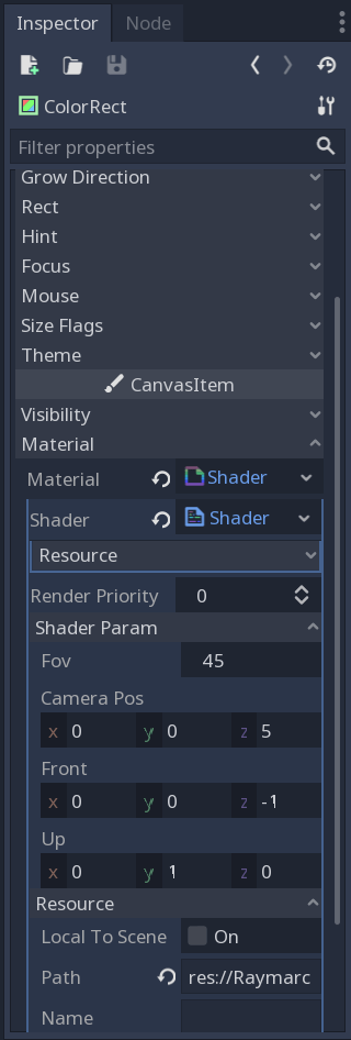
Change the fov to 90 and front to the (0, 0, 1). Run the application. You should see similar result:

That’s it for now. A little boring, I know. In the next chapter we are finally going to draw some objects. Until then, cheers!

Thanks for the great tutorial! Just wondering if you could go into a little more detail regarding the view angle. Why does it need to be divided by 2 after being converted to radians?
LikeLike
Hey Geoff, glad that you’re finding this post useful!
Basically I have a target Field Of View in my mind that corresponds to what you see in games (between 45-90 degrees). That’s the angle between the top and bottom rays going from the camera.
In our calculations we are interested in the angle between our forward ray and top/bottom ray, which is exactly 1/2 of the FOV angle. I’ll try to add an illustration in this blog a bit later on.
LikeLike