
Emulators
So… what is an emulator?
Let’s say you want to play an old game from the MS-DOS era. You have the DUKE3D.EXE file, you launch it and …
nothing happens. But why?
Old systems had a different architecture from your PC. Loosely speaking, your PC doesn’t recognize the program and refuses to execute it. You have to find an adapter that can translate the program to something your PC can understand. And there you have it, emulators!
We will be writing a CHIP-8 emulator for the modern computers. It will take a binary file (aka ROM, Read Only Memory) that a CHIP-8 Virtual Machine (VM) could read and execute it as if your PC was a CHIP-8 machine.
CHIP-8?
Let’s take a look at the CHIP-8 itself. What exactly is it? A quick glance at the Wiki page tells us that it’s an interpreted programming language. Think of it as a super early version of Java. You could write a game for the CHIP-8 and run it everywhere. Everywhere the CHIP-8 Virtual Machine was implemented for, that is. We are going to re-implement the VM and run some CHIP-8 games as if it were 1970-s again.
So, we have a CHIP-8 ROM. What do we do with it? What is a ROM anyway?
A ROM is basically a binary program code with all the data we need to execute it. Your NES cartridge is a ROM. Your BIOS is a ROM. You cannot modify it, hence the name. ROM contains both the code and embedded data like icons, sprites and audio tracks.
We will start by implementing a processor and make it execute our ROM file. It will need a virtual RAM, a virtual display to render pixels to, a virtual keyboard to read the input from, a random number generator and 2 timers. You can find this information in the CHIP-8 documentation. It describes how the VM works, what systems does it have, what instructions VM supports and much more. You will find yourself constantly going back to it during the coding part.

Memory
Let’s start with the memory first. CHIP-8 didn’t have a virtual memory model like our modern operating systems do. In fact, it treated memory as if it was a contiguous array of bytes. It was capable of accessing up to 4 KB of RAM data. Each byte has an offset associated with it – from 0x0000 to 0x0FFF in hexadecimal notation.

The first 512 bytes (ending at the 0x200 address) are reserved for the VM implementation. It also contains sprites of the hexadecimal digits (more on that later). We should load our ROM after the 0x200 offset according to the documentation. That means that CHIP-8 ROMs cannot exceed 4KB – 0.5KB = 3.5KB in size – otherwise CHIP-8 just cannot fit it into the memory!
You might be wondering – what it a hexadecimal notation? Why would I want to use it? To put it simply, a hexadecimal number is using 16 digits instead of 10 digits – 0,1,2,3,4,5,6,7,8,9,A,B,C,D,E,F. We will add ‘$’ or ‘0x’ to a number so you will not confuse the two. For example, number 35 in decimal notation is equal to 0x23 in hexadecimal. You can play around with hex numbers here.
We use it because a single byte (or 8 bits) can be conveniently depicted by 2 hexadecimal digits. This also means that 1 hex digit can store 4 binary digits, also called a nibble or half-byte. For example, 235 in decimal is equal to 11101011b in binary and 0xEB in hex. Another neat property is that we can clamp bytes together to form one long hex number. 4 bytes can be encoded as 8 hex digits. For example, 0xDEADBEAF depicts 4 bytes – 0xDE, 0xAD, 0xBE, 0xAF. The same number is 11011110 10101101 10111110 10101111b in binary. As you can see, hex number is much more compact.
Later on we will discover that every CHIP-8 operation code is encoded by 2 bytes of data read directly from the RAM.
So we will start with creating a 4 KB array of bytes and call it a virtual RAM. We will read a ROM file and put it in our virtual RAM at the offset of 512 (0x200). What next?
ROM – Read Only Memory
If you open a ROM file with a hex editor (HdX or GHex will do) you will see that it is not comprehensible by human. What you see is a binary version of the program that is fed directly to the processor.

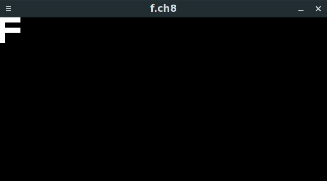
In the figure above you can see a simple program that draws a single digit F to the screen. This is a tiny program consisting of mere 10 bytes of code. It has 5 CHIP-8 instructions. How do I know it? Because every instruction is 2 bytes long!
The first instruction is 0xA04B. The second one is 0x6000. We will see what they do when we get to the instruction part of the tutorial. For now all you need to know is that the processor recognizes around 35 instructions and each one has a fixed size of 2 bytes.
Processor
The CHIP-8 processor works in the following way.
- Read the value of a special PC register.
- Fetch an instruction (2 bytes) from the RAM at the offset (aka address) PC.
- Move PC to the next operation 2 bytes forward (PC := PC +2).
- Execute the command encoded by the instruction we fetched on step 2.
- Repeat step 1.
- (Optional) Crash if instruction is invalid.
This cycle repeats itself until you halt the machine or it encounters an error instruction (unknown command encoded by those 2 bytes).
But wait, what is a register? A register is a very small named variable built into the processor. It has a fixed name and a size. CHIP-8 has:

- 16 general purpose (meaning that you have a direct access to them as a programmer) 8-bit registers called
V0, V1, …, V9, Va, Vb, Vc, Vd, Ve and Vf - 16-bit general purpose register I – we use it to store addresses
- 8-bit special register DT – delay timer
- 8-bit special register ST – sound timer
- 16-bit pseudo register PC – program counter
- 8-bit pseudo register SP – stack pointer (more on this later)
You can use V0 and its friends to add numbers, read values from the RAM, store offsets and many-many other applications. You will learn more about them when we get to the instructions.
A processor also has 2 very special registers – PC and SP. PC (program counter aka instruction pointer) is storing the offset (aka address) of the next instruction. Next processor cycle will read and execute whatever operation is stored in the RAM at this location. It has to be at least 12 bits in size because the largest offset in a CHIP-8 program is 0x0FFF – 1 byte and a nibble in size. But since we don’t want to slice a byte, it is a 16-bit, or 2 bytes, register. Its upper half-byte is unused.
SP is a Stack Pointer. It is pointing at the top of the stack and it is an 8-bit register. But what is a stack? It is a fixed size storage that grows in one direction. You can put a value on top of the stack. You cannot access values below the top value unless you pop all items lying on top of the desired value.

Usually stack is located in the RAM, the same RAM we are using for our program. But CHIP-8 has a separate stack memory space, so you cannot access it directly. It has 16 slots, 2 bytes each, and grows 2 bytes at a time. If stack size is at its limit, the top of the stack overflows to 0 and overwrites whatever value we had there. Of course, this is dangerous and can lead to some peculiar bugs.

Now let’s discuss one important application of the stack – function calls aka subroutines.
At the start of the program stack is empty and SP is set to 0. When we call a subroutine in our game, CHIP-8 will push our current PC value onto the stack and increase SP by 1. It also sets PC to the address of the function we are calling. If we call one more subroutine, it will push our current PC onto the stack again, setting SP to 2. When we return from the subroutine, CHIP-8 takes whatever is at the top of the stack and sets PC to this value, decreasing SP by 1 afterwards.

Okay, that’s a lot of information, how much more there is to it? Thankfully not too much 🙂
Keyboard
Let’s blast through the keyboard first. CHIP-8 assumes that your keyboard looks something like this:

All we have to do is to bind part of our keyboard to this virtual keyboard just as on the figure above.
CHIP-8 can (but doesn’t have to) halt execution until a key is pressed. It then stores a key code to the processor register and continues executing our program.
Graphics
CHIP-8 also assumes that you have a display. It has a whooping resolution of 64×32 pixels. Pixels flow from LEFT to RIGHT, from TOP to BOTTOM. Every pixel has 2 colors. We will choose a classic white and black palette.
But you don’t just draw one pixel at a time. That would be too tedious. Instead you draw a sprite. What is a sprite exactly? It’s an image 8 pixels wide and X pixels tall. X is a number between 1 (1 row of 8 pixels) and 15 (15 rows of 8 pixels). Each bit of the sprite represents 1 pixel.
For example, 0x87F0, or 1000 0111 1111 0000, is a sprite that is 8 pixels wide and 2 pixel tall. Its first pixel is white followed by 4 black pixels followed by 3 white pixels. It then switches to a lower row with 4 white pixels and 4 black pixels.
All sprites are in the ROM, coexisting with the game code. This means that during execution we are storing our sprites in the virtual RAM. One curious implication is that you can accidentally draw an instruction instead of a sprite, producing garbage on the screen. CHIP-8 cannot distinguish sprite from an instruction, so it won’t crash the program.
Remember our scheme of the memory layout from way before? CHIP-8 VM reserves first 80 bytes for the hexadecimal digit sprites, 0 through F. Each sprite is 8 pixels wide (as any sprite) and 5 pixels tall, so each one takes 5 bytes of memory. We have 16 of them, so they take 16×5=80 bytes total of our RAM.

There is an instruction to draw a sprite to a screen. You give it an X and Y offset on the display, an address of the sprite and its length and it draws it onto the screen. If it doesn’t fit, the remainder overflows to the opposite side of the display.
CHIP-8 is drawing sprites in a peculiar way. It is not blindly overwriting the pixel on the display. It is applying XOR (eXclusive OR) bit-wise operation on the display pixel and a spite pixel. Here what it looks like:

Okay, we are almost at the end!
Other Components
CHIP-8 can also play music! Nah, I’m just kidding, it can beep in one sound for a while. You can make it beep by executing a special instruction that sets up a timer register ST. VM is decreasing its value at the rate of 60Hz. This is a fancy way of saying that ST is decreasing its value 60 times every second until it is equal to 0. CHIP-8 will beep for as long as ST value is not 0.
CHIP-8 also has a DT timer register that works essentially the same. However it is not tied to a sound. And you can access its value using – you guessed it – a CHIP-8 instruction.
CHIP-8 can also generate random numbers. There are no specifics, so any RNG will do. I personally use this one from the GDC talk because it is easier to use with unit tests.
And this is all that CHIP-8 has to it. It’s just a processor that can address up to 4KB of data. It has 16 8-bit general purpose registers, one 16 bit register for storing addresses, a program counter PC, a 16 byte stack, a display, a beeper, a keyboard and 2 timers. To run a CHIP-8 program you have to implement (aka emulate) every component.
Congratulations on making this far! You have done the trickier part of writing an emulator – understanding what the heck to do! Emulation is a very challenging problem, but also a very rewarding one. You essentially learn how computers work by implementing one yourself!
Please let me know if you find this post useful. If it gets enough attention I can make a follow-up CHIP-8 emulator tutorial where we implement it.
Until next time!
